KiCad hardware design files for the MostlyBuilds Speaker Pod, a custom smart speaker built around an ESP32, touch display, and mono I2S amplifier.

MostlyBuildsSpeakerPod.kicad_pro- KiCad project fileMostlyBuildsSpeakerPod.kicad_sch- schematicMostlyBuildsSpeakerPod.kicad_pcb- PCB layoutmedia/Schematic-V0R0.pdf- schematic PDF for quick referencelib/symbols/- project-local KiCad symbolslib/footprints/- project-local KiCad footprintslib/3d/- project-local 3D component models
V2 is the current version of the Speaker Pod. For the complete story and build context, watch the original V1 build followed by V2.
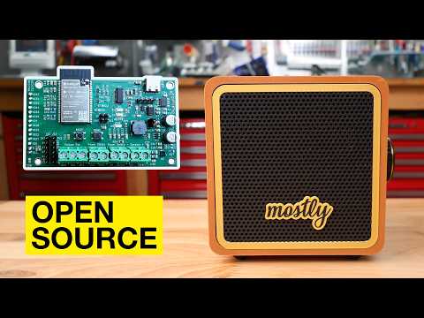
▶ Watch the V2 build on YouTube
V1 covers the original design and the foundation carried forward into V2.
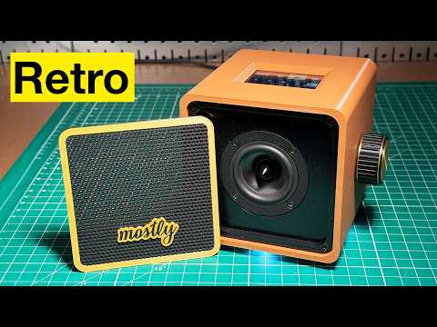
▶ Watch the V1 build on YouTube
- V2 build article and complete parts list - start here for all current V2 build parts, including parts unchanged from V1.
- V1 build article and parts list - original build details and the V1-specific parts list.
- PCB component BOM on DigiKey - electronic components used to assemble the PCB; this is not the parts list for the complete speaker.
- Order the PCB through PCBWay - available as a bare PCB or fully assembled board.
- Light Pod PCB - design files for the companion lighting board.
- Power: USB-C supplies 5 V.
IC1(MIC2549A) switches the downstream 5 V rail, andIC2(AP63301) generates 3.3 V. A 10K combination switch/potentiometer connects toJ1(power) andJ5(volume). For bench testing, bridge theSWCHheader (J2) or add a jumper atJ1. - Controller: The
ESP32-WROVER-E-N16R8provides Bluetooth Classic and PSRAM for audio playback, the graphical interface, and multiple playback modes. - Audio:
U2(MAX98357A) is a mono I2S Class-D amplifier. Its differential output is available at the speaker terminal (J9) and was designed around the 4 ohm Dayton Audio RS75-4. - Display: The 14-pin footprint is for the linked 2.8 inch 240x320 IPS capacitive-touch ILI9341V module. Similar-looking modules may have different pinouts or dimensions, so verify compatibility before substituting one.
- Programming: USB-C data connects to an onboard
FT231XSUSB-to-UART interface with ESP32 auto-reset circuitry. Boot and reset buttons are also provided. USBGND,5V,D+, andD-are broken out for testing. - Debugging: JTAG is exposed at
J11.GPIO14also reaches screen reset through 0 ohm resistorR15, andGPIO13reachesSD_CSthrough 0 ohm resistorR16. Remove the relevant resistor if a shared signal interferes with JTAG; doing so disables that associated function.
Open MostlyBuildsSpeakerPod.kicad_pro in KiCad. The required custom symbols,
footprints, and 3D models are included under lib/, making the project portable
without separately installed libraries.
These files use KiCad 7 format markers (kicad_sch version 20230121, kicad_pcb version 20221018). Use KiCad 7 or newer unless you intentionally migrate the design.
Generated fabrication outputs are not committed here. Plot Gerbers, drill files, and any assembly documentation from KiCad after reviewing the current schematic, PCB layout, design rules, and fabrication requirements.
This project is provided as-is by a hobbyist. Review the design carefully and use your own judgment before building, modifying, or manufacturing it.
This project is licensed under the Creative Commons Attribution-ShareAlike 4.0 International Public License.
See LICENSE for the full license text, or visit: